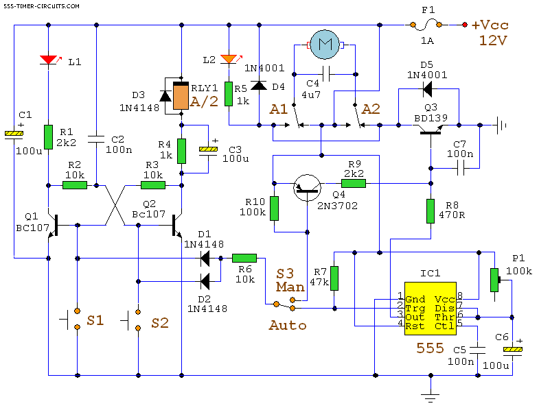
AUTOMATIC CURTAIN CLOSER Circuit

This circuit uses a mixture of transistors, an IC and
a relay and is used to automatically open and close a pair of
curtains. Using switch S3 also allows manual control, allowing
curtains to be left only partially open or closed. The circuit
controls a motor that is attached to a simple pulley mechanism, to
move the curtains.
Automatic Operation
The circuit can be broken into three main parts; a bi-stable
latch, a timer and a reversing circuit. Toggle switch S3 determines
manual or automatic mode. The circuit as shown above is drawn in the
automatic position and operation is as follows. The bi-stable is
built around Q1 and Q2 and associated circuitry and controls relay
A/2. S1 is used to open the curtains and S2 to close the curtains.
At power on, a brief positive pulse is applied to the base of Q2 via
C2. Q2 will be on, and activate relay A/2.
The network of C3 and R4 form a low current holding circuit for the
relay. Relay A/2 is a 12V relay with a 500 ohm coil. It requires
slightly less current to keep it energized than it does to
operate it. Once the relay has operated, the current through the
coil is reduced by R4, saving power consumption. When Q2 is off, C3
will be discharged, but when Q2 becomes active (either at switch-on
or by pressing S1) capacitor C3 will charge very quickly via the
relay coil. The initial charging current is sufficient to energize
the relay and current flow through R4 sufficient to keep it
energized.
View All Circuits


